![]()
![]()
![]()
![]()
![]()
![]()
| NEW WORKTOWN LAYOUT ! The baseboards for the new worktown layout have finally been started! This will be about 7'6" by 18" but will fold in half for easy transport and storage. I'm sticking with the same era and area but the new layout will have more space for the static bus models to be displayed, while still enabling space for the motorised fleet to circulate. I will be making use of the Hornby Skaledale and Bachmann Scenecraft buildings as well as scratchbuilding some of the more complicated structures. Hopefully the "fold-up" design of the layout will mean better protection for the scenery this time. This should allow me to (possibly) have working lights and maybe a few trolleybus wires eventually. Pictures will be added to this page as time allows. |
||
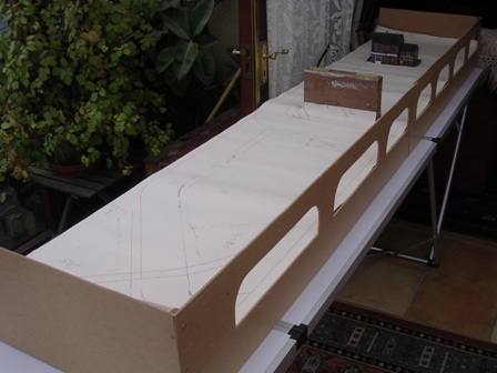
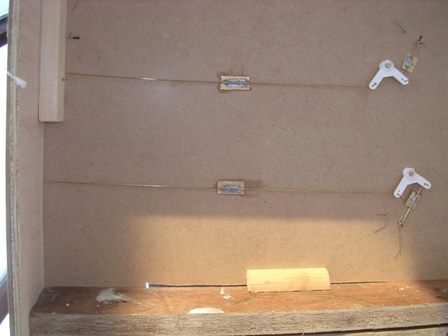
| First picture of the baseboards for the new Worktown layout. The
large wooden block thingy in the middle is the hinge point where the
layout folds in half. The back-board has access holes to retrieve any
buses that stop or otherwise come to grief! There will be an inner
backscene behind which the buses will run and turn in from. The
wallpaper laid out on the surface is a full size plan of the "trackwork". The building in the background was retrieved from the old Worktown and is a scratchbuilt model of an off-license which was on Halliwell Road in Bolton.
|
 |
|
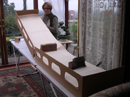
| A quick demo showing how the baseboards fold up. The top surface of
the board is 7mm MDF on a frame-work of mostly 6mm plywood and the hinge
is on some pieces of 3/4" blockboard I found in the shed. I have yet to make an "end piece" to lock the folded up layout together for carrying. A removable building will be made to cover up the hinge unit when the layout is set up. Probably a Town Hall type thing or something grimy, victorian and vaguely industrial. (Cheers Ruth, you can put that end down now!)
|
 |
|
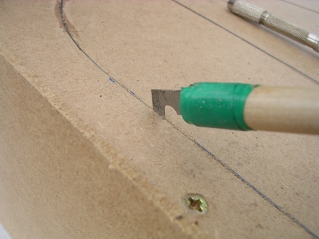
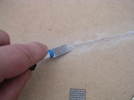
| Rather than use the standard Faller track wire as supplied in the
starter kits, I have decided to use 24swg piano-wire. This is usually
available in 1metre lengths from model shops. I chose this as it is
slightly thicker than Faller wire, and helps the steering magnets
control the heavier die-cast buses. I use an OLFA cutting blade (designed for scoring plasticard) to cut a groove for the wire. Make sure you keep the blade vertical to keep the groove slim. That way the groove is exactly the right width for the wire. Try to keep the depth of the cut to a little more than the thickness of the wire. Clean out the groove with a small brush. The usual warnings about not breathing in MDF dust apply here! Have a practise on an off-cut of MDF until you can just press the wire into the groove so that it is just flush with the road surface.
|
 |
|
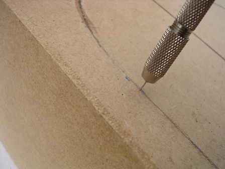
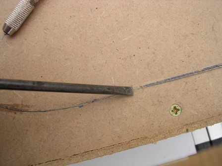
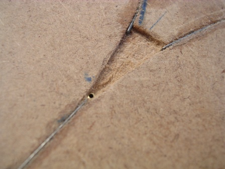
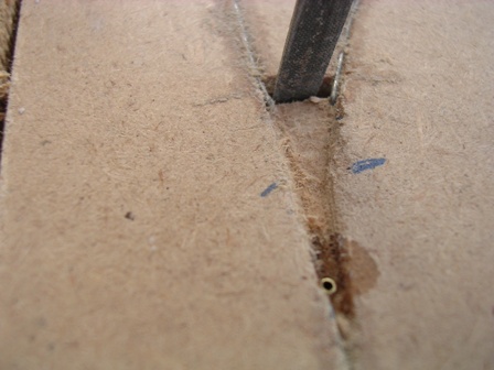
| As a starting point, drill a hole in the groove right through the
board (0.6mm) or whatever the thickness of the wire you are using. This
provides a strong location point to start a wire run from and stops it
twanging out of the groove as you start .
|
 |
|
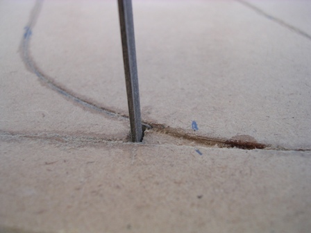
| Put a 90 degree bend in a piece of track wire (bend about 7-8mm) and
press the bent end into the previously drilled hole. WARNING! When cutting or bending piano wire, take care as it is hard and springy and can twang up and injure you. Take especial care if cutting a short length off as small lengths can fly at surprising speed and will easily puncture the skin or damage an eye.
|
 |
|
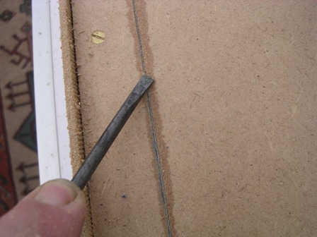
| You can then lay the wire into the groove and press it in with the
end of a screwdriver until it is flush with the road surface. If your
groove cutting technique is OK the wire will probably sit nicely in the
groove without pinging out!
|
 |
|
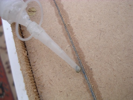
| When you are happy with the fit and finish of that section of wire
it can be secured in place with a good quality superglue. I use ZAP CA glue although other products may do the job just as well. You shouldn't need too much glue, just enough to wet the wire and a little of the surrounding board.
|
 |
|
| Any wire that won't stay in the groove on it's own or sticks up
proud of the surface can be held down until the glue sets. Should be
about 40-60 seconds depending on the glue. Any wire that argues can be re-glued and pressed in until it stays! Oh, and don't glue the screwdriver to the wire (like I did.....)
|
 |
|
| The surface can now be levelled by applying a small smear of filler
with a spatula.
|
 |
|
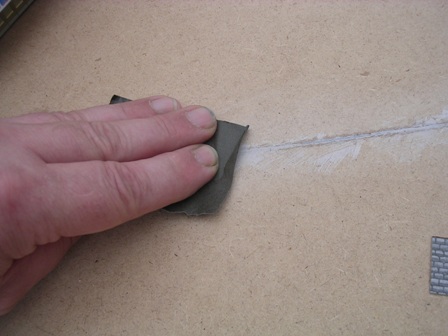
| Finish off by sanding the surface with a fine sandpaper or wet and
dry and don't forget the warnings about MDF dust. You should now be ready for a test run with a suitable vehicle.
|
 |
|
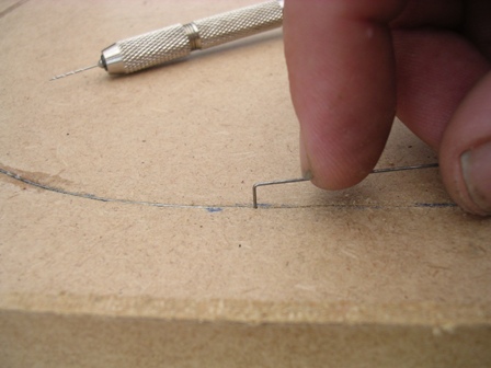
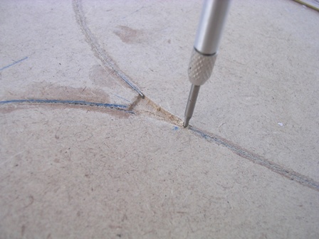
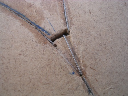
| At this stage you'll realise that a method has to be found for
diverting the buses on to a different route occasionally. Where the
diverting points are going to be, terminate the wires in a way that
separates the routes sufficiently so that a steering magnet cannot
randomly choose it's own route. Mark a triangle between the 3 ends of
wires and carve out a recess as shown in this picture and the next one.
It will need to be a little deeper than the wire thickness. At the
leading end of the point, a moveable section of guidewire will be
installed that pivots in a brass tube through the baseboard. Choose a
size of tube that is just big enough for the wire to pivot in, and drill
a hole the same size as the brass tube as shown here
|
 |
|
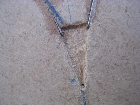
| A typical point recess is shown here with a hole drilled at the
leading end, ready for the pivot tube.
|
 |
|
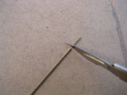
| Cutting small bore brass tube is quite easy. I have cut about 10mm
off for the pivot. Using a new blade in your craft knife, gently press the blade on to the tube and roll the tube backwards and forwards to score a ring around the tube. Keep it straight so you have one line and not a spiral along the tube. This is just a smaller version of a pipe cutter that a plumber would use. When the scored ring mark appears on the tube it should be then possible to gently snap off the tube leaving a clean edge. If you press too hard or keep cutting for too long the piece will probably ping off and disappear, so stop before you cut all the way through. You'll get the idea with practise! |
 |
|
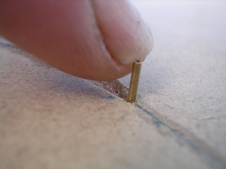
| Gently press the cut tube into the drilled hole so that it is flush
with the bottom of the recess and is poking out a little under the base
board
|
 |
|
| The pivot pipe in its correct location in the recess
|
 |
|
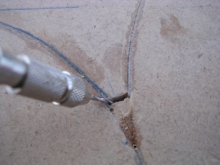
| The next job is to cut a slot through the board at the wide end of
the recess. This is for the pivot wire to swing in and to correctly
locate against each guidewire route. (See further down for pivot wire
details)
|
 |
|
| I used a small needle file to enlarge and adjust the slot as
required. Note also that the pivot tube has been secured in position
with superglue
|
 |
|
|
|
 |
|
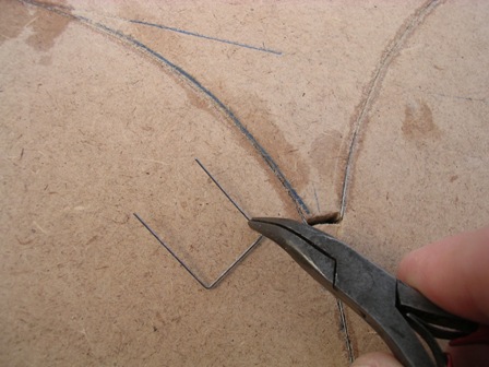
| Now you can bend a piece of guide wire as shown in the picture. You
are looking to fit the wire between the pivot hole and the guide slot so
that it swings freely between the two routes and touches each of the
ends of the guide wire, so that the steering magnets can follow each
chosen route.
|
 |
|
| Fit the wire as shown in this and the next picture and check it
moves properly to it's limits of travel
|
 |
|
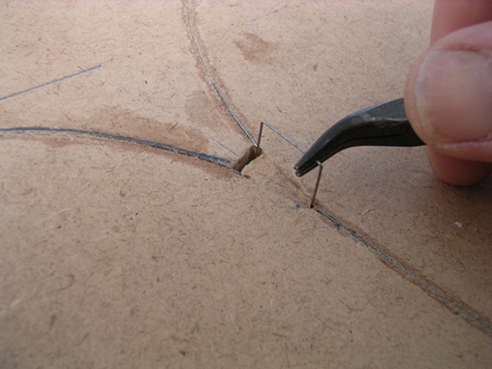
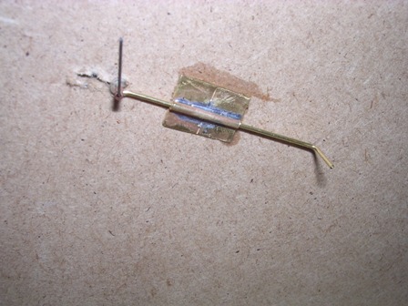
| This wire has been located correctly but is in mid-travel. When in
position, it should lie horizontally in line with the other 3 wires and
not above or below as this will deflect the steering magnets on your
vehicles. You may need to make adjustments to the bends on the wire to
get correct alignment.
|
 |
|
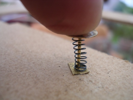
| When all is ok with the alignment, go under the baseboard and bend
over the wire where it comes out of the tube, making sure that the wire
is still pushed fully into the tube. This is to keep the wire located
correctly. The other end of the wire is used to connect to an operating
rod so you can work your points remotely. I won't go too deeply into methods of operation as they are many and varied but I prefer manual where possible. The one shown here is brass rod, sprung loaded to hold it towards the "main" route.
|
 |
|
| This operating rod runs through a brass tube and has been set ready
to connect to an angle crank to turn the operation through 90 degrees.
|
 |
|
| Sprung loaded plunger on the end of a short operating rod through
the edge of the baseboard sideframe
|
 |
|
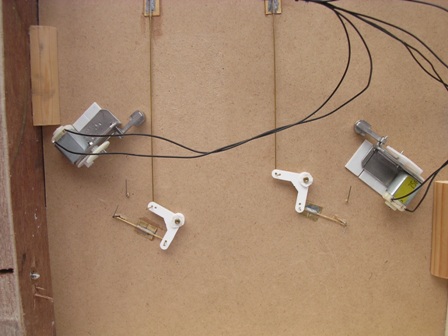
| These 2 points (seen from under the baseboard) had to be fitted with
angle cranks to turn the rods toward the edge of the baseboard. All
operating rods are made from brass wire to avoid unwanted magnetic
attraction of the steering magnets.
|
 |
|
| As well as points, This area now has some magnetic stops fitted.
These work by activating the reed switches fitted to the vehicles. I'll go into this in more detail in future sections.
|
 |
|
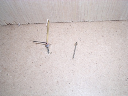
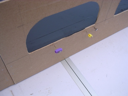
| 3 of the operating rods for the points. The two with coloured
handles can be set for different routes and left in position, and the
little one on the right is sprung loaded and will operate when pressed
and held and should always (hopefully) return to the main route
when released.
|
 |
|
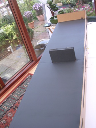
| When I had laid all the track and made up the points, I had a good
test run with each bus to make sure all was in order. Paper stickers or
labels can then be cut to size and layed over the points recesses to
cover them up. All can then be painted over with a suitable "roady" sort of colour. I used water based blackboard paint with a bit of white emulsion mixed in. It had a good testing at the MBF Chester do in October which showed up a few problems which will be dealt with in due course. (Mostly caused by my bad planning and rushing to get it running in time!!!!)
|
 |
|
| Well it's been a while but here are a few pics of the current state
of play on the layout. It was taken to Chester Model Showbus in October 2011 and performed quite well. There are still quite a lot of details and operational improvements to add although and extra connection in the roadway added to the operational flexibility.
|
||
|
|
||